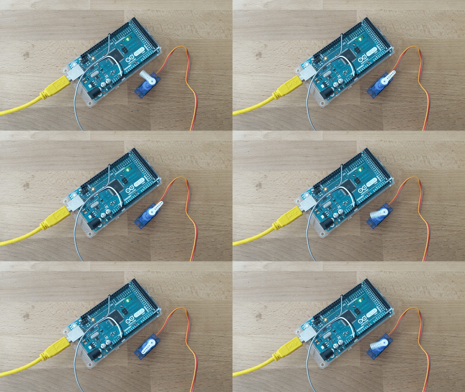
Need to move something in your project? Add a servo motor! In this tutorial we will cover the basics of controlling a servo motor and some tips on calibrating your servo motor to get the full range of motion. Let's get started!
Step 1: Connecting the Servo Motor
Common servo motors such as the SG90 servo and the MG90S servo come with a connector with 3 pins, one for connection to a 5V DC power source (usually red), one for connection to ground (usually black or brown) and the last one for controlling the position of the servo arm. (usually yellow, orange or white)
A typical connection to an Arduino is shown below:

I used an Arduino Mega here, but any other Arduino would work fine. Just make sure that the signal pin of the servo motor is connected to an output pin of the Arduino capable of pulse width modulation (PWM).
NOTE: On Arduino boards other than the Mega, the use of the Servo Library will disable the PWM functionality on pins 9 and 10. On the Mega, if more than 12 servos are used, the PWM functionality will be disabled on pins 11 and 12.
Step 2: Controlling the Servo
To control the servo motor, we can use Arduino's built-in Servo library. Here we have written some code to make the servo motor turn to the 0° position, wait for 3 seconds, turn to the 180° position, wait for 3 seconds and repeat the process.
Let's go through some key lines of code used.
- #include <Servo.h> : Imports the Servo library to easily interface with the servo motor
- Servo servoMotor; : Creates a Servo object called servoMotor.
- servoMotor.attach(servoPin); : Tells the library which output pin on the Arduino to associate with the servoMotor object. Find out more here.
- servoMotor.write(0); : Sends a signal to the motor to go to the 0° position. Find out more here
And thats all the code you need to control the servo however you want! However, if your realized that your servo motor is not rotating the full range of motion of 180°, you might need to calibrate your servo at the next step.
Step 3: Calibrating the Servo
A servo motor uses pulse width modulation (PWM) to understand which position the servo motor should turn to. The Servo library allows us to easily control the motor position in degrees by converting the degrees we specify into the microseconds of the pulse width required to "tell" the servo motor which angle to turn to.
If we look at the documentation for the .attach() function, we see the following:
Syntax
servo.attach(pin)
servo.attach(pin, min, max)Parameters
servo: a variable of type Servo
pin: the number of the pin that the servo is attached to
min (optional): the pulse width, in microseconds, corresponding to the minimum (0-degree) angle on the servo (defaults to 544)
max (optional): the pulse width, in microseconds, corresponding to the maximum (180-degree) angle on the servo (defaults to 2400)
We can see that the minimum pulse width that corresponds to the 0° position defaults to 544, while the maximum pulse width that corresponds to the 180° position defaults to 2400. However, these values are not always true for every make and model of the servo motor you bought. In fact, in my experience, even within the same make and model of servo motors, these max and min pulse widths differs slightly as well.
Therefore, if your servo motor is not turning to the full range of motion which you expect, try either reducing the minimum or increasing the maximum pulse width in microseconds using the servo.attach(pin,min,max) function. I found that for my servo, having 500 as the minimum and 2450 as the maximum pulse width did the trick!
That's all for this tutorial, hope it has helped some of you makers out there! If you are still having issues, feel free to leave a comment and I'll try my best to help you out!


