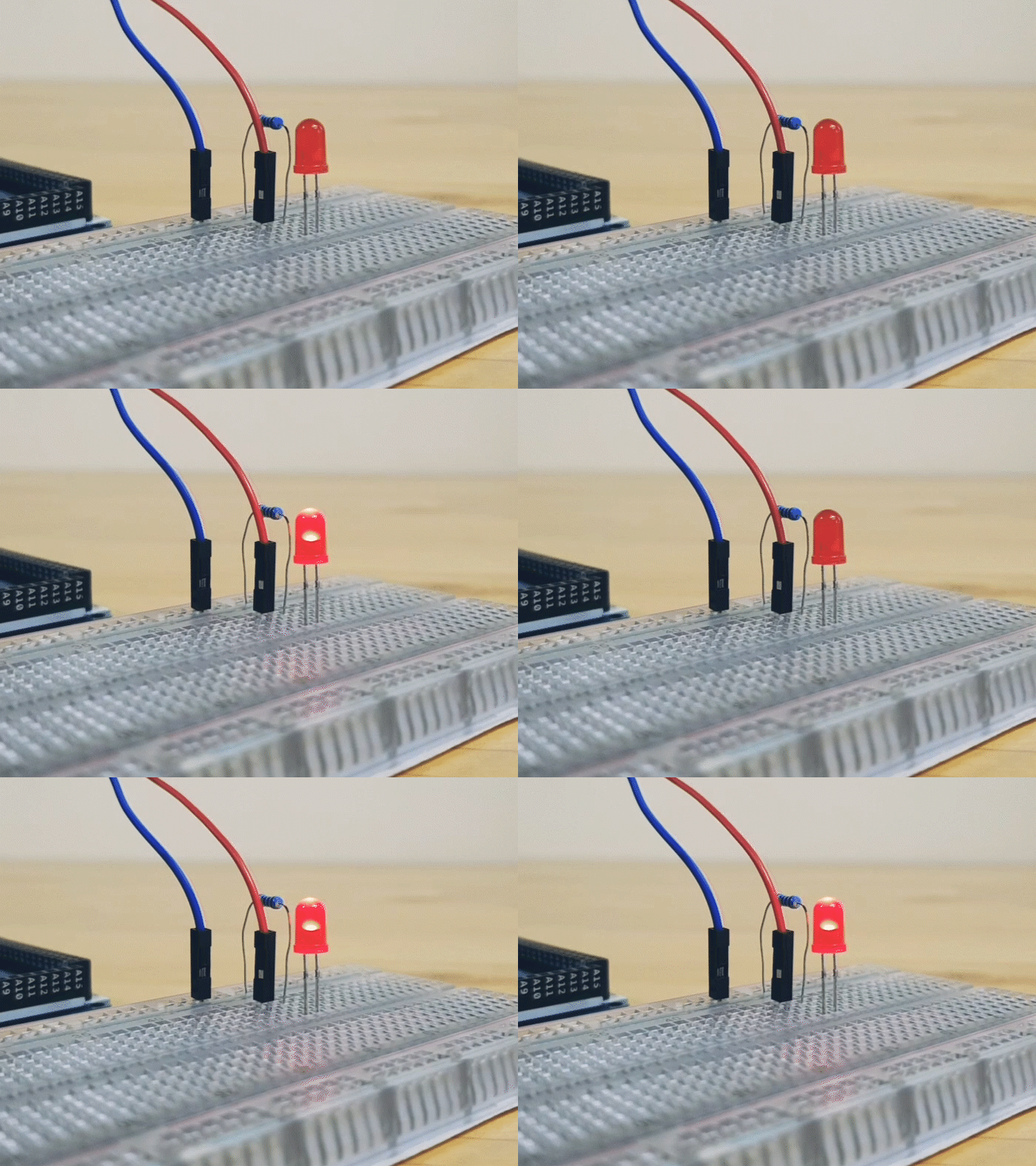
There are so many things you can do with an LED in a circuit - mainly for signal communication and aesthetics. For a start, let’s try to make an LED blink with an Arduino microcontroller.
Time Taken: 5 mins
What You Will Need:
- 1 x Resistor (220 Ohm, or a value as close to this)
- 1 x LED
- 2 X Male to Male Jumper Wires (minimum)
- Arduino Uno Microcontroller
- Arduino Uno Cable
- Laptop/Computer
- (Optional) Power source e.g. power bank or battery
Steps:
1) Setup the circuit as shown below:
🔥 DANGER: LEDs have polarity. Connecting the positive and negative ends wrongly will likely spoil your LED. The positive end is usually longer than the negative end. The negative end connects to the resistor before joining the rest of the circuit.
🔥 DANGER: LEDs are not current limiting! That means that if there is no resistor in place, the LED will just draw as much current as possible from the Arduino which will cause the LED to burnout!
2) Connect the Arduino to your computer using the data cable
3) Open Arduino IDE and select the port corresponding to your Arduino under (Tools > Port)
⚠️ POTENTIAL PITFALL: Ensure that you choose the correct port as failure to do so will cause issues when trying to upload your code!
4) We begin by defining some variables to be used in our script.
For simplicity's sake, we use the integer data type represented by 'int' however, since these values will never be negative, you could use unsigned 'int' as well.
✨ FUN FACT: Arduino Microcontrollers have a built-in LED on pin 13 that’s frequently used to indicate an action or event.
5) Next, in our setup function, we need to define what mode the pins operate in,
Using the ‘pinMode’ function, we set the pin connected to the LED to be an OUTPUT pin. This way, we can use the Arduino to send commands to the specified pin.
6) Next, in the ‘loop’ function, we will set the microcontroller to alternate between sending a high voltage and low voltage to the pin for a specified time period.
The function ‘digitalWrite’ allows us to set the voltage of the pins at 5V (turns on the LED) or 0V (turns off the LED) using the keywords ‘HIGH’ and ‘LOW’. To set how long the pins will be in those states, we use the ‘delay’ function, which will effectively pause the script from running for the amount of milliseconds stated.
7) Click upload and watch your LED come to life! 💡
Full Code:
Simple Variations
- Adjust the blinking speed: Change the delay time. (Remember to write in milliseconds!)
- Add more LEDs: Duplicate the lines at each section and replace names to the corresponding pins
- Make lights dimmer: Replace the 220 Ohm resistor with a greater value resistor (e.g. 1k Ohm, 10k Ohm)
Troubleshooting Suggestions
- If it does not light up, check your solderless breadboard’s default connections!
- If the MC has been used previously (aka has other code on it), you may need to press the reset button (does not delete your code) on your microcontroller to get it going.
Do share your projects with us on Instagram by tagging us @makersupplies.sg
Resources:


